![]()
Menu
Velleman K8055 USB Experimenter Board
Universal Serial Bus (USB) Connectors
The USB is a serial bus. It operates by sending fast serial communications over the signal wires. USB has multiple protocols with different data rates.
USB Speeds and Protocols
- Low SpeedOperates at 1.5Mb/s and is used primarily for HID (human input devices, such as mouses and keyboards).
- Full SpeedOperates at 12 Mb/s and is the most widely supported format.
- Hi-SpeedOperates at 480 Mb/s and is the most widely supported format. USB 2.0 includes Hi-Speed USB specifications, but not all USB 2.0 are Hi-Speed.
- Super SpeedOperates at 4800 Mb/s and considered USB 3.0
| Pin | Name | Cable color | Description |
|---|---|---|---|
| 1 | VCC | Red | +5 VDC |
| 2 | D- | White | Data - |
| 3 | D+ | Green | Data + |
| 4 | GND | Black | Ground |
 USB Pins USB Pins |
|---|
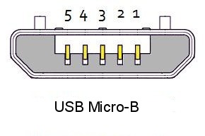
| Pin | Name | Cable color | Description |
|---|---|---|---|
| 1 | VCC | Red | +5 VDC |
| 2 | D- | White | Data - |
| 3 | D+ | Green | Data + |
| 4 | ID | n/a | USB OTG ID |
| 5 | GND | Black | Ground |
 USB Pins USB Pins |
|---|
Speed Identification
A USB device must indicate its speed by pulling either the D+ or D- line voltage high to 3.3 volts. A full speed device, uses a pull up resistor attached to D+ to specify itself as a full speed device. These pull up resistors at the device end will also be used by the host or hub to detect the presence of a device connected to its port. Without a pull up resistor, USB assumes there is nothing connected to the bus. Some devices have the pullup resistor built into its chip set, which can be turned on and off under firmware control. Other devices may use an external resistor.
USB Load and Voltage
USB devices are bus-powered, which menas that they obtain their power from the bus connection and do not require external connection to a power source. Higher power bus connections work at a minimum of 4.4VDC and its specified to a maximum of 5.25VDC. USB busses connect at 200mAh to 500mAh maximum.
USB Communications
USB transactions consist of token packets (the header), an optional data packet (the payload) and the status packet, which is used to indicate error conditions and provide error-correction. Packets communicate with PID Values, which indicate the fields for the types of packets send. This half-word (4 bit) connection string has standard identifiers which indicate which type of signal to include. The standard packet types are broken down into three types: In, Out, and Setup.
K8055 Experimenter Board
The K8055 USB Interface Board Kit is designed by Velleman. It's available from the Velleman K8055 Kit. The kit assembles in an afternoon and for all intents and purposes, it is well-organized and the instructions are very clean. I assembled it a couple of hours.
K8055 Assembled Assembled in Two Hours |
|---|
The K8055 board has five digital input and eight digital output channels. There are also two analog inputs and two PWM (pulse width modulation) inputs. By changing the jumpers on SK3 and SK4 and SK5 and SK6, you can specific up to four different channels for four simultaneous boards. Also, use of the board with a computer device is installation of the k8055d.dll into your System32 or SysWOW64 folder.
The K8055 board has five digital input and eight digital output channels. There are also two analog inputs and two PWM (pulse width modulation) inputs. By changing the jumpers on SK3 and SK4 and SK5 and SK6, you can specific up to four different channels for four simultaneous boards. Also, use of the board with a computer device is installation of the k8055d.dll into your System32 or SysWOW64 folder.
What To Do With It
You can use the K8055 as a good interface for modules (as long as the input doesn't exceed +5VDC) that either input through USB connection or you can output through the K8055 to display signals on the board. I also found a site where Brian Moreau was experimenting with the K8055 over HTTP control using Ajax. The interaction over HTTP is a bit flakier, but once you get it configured for your system properly (including getting the MSINET.OCX installed, it does provide some entertainment.